Rotary Indexer - Overview 2
As I have been otherwise engaged and very busy over the last couple of years I haven't managed to publish for quite a while so I just thought that I would write a catch up article on the rotary indexer project. I have retained the original ABS case even though I did make a d.i.y. case to show that it could be possible to reduce costs to a minimum. Overall I think that the whole project , not including stepper motor was less than £30.00 and that included the Maplin ABS case.
I made up a label for the front of the control box which I had laminated and then fixed to the front of the controller. I have also completed the hardware to connect the stepper motor to my small rotary table. The original motor I bought is capable of controlling a much larger device so I replaced it with a smaller motor. I've added a few pictures below with a short description of each


Rotary controller with the label showing the button legend fixed in place. I was pleased that the cut out for the display fitted so well. I printed this out with high quality (supposedly) fade free Epson photo inks.
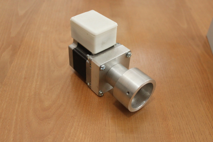
Three quarter view of the connecting collar and stepper motor. This shows the box on the motor well. This houses the 6 pin female aero socket and sits over the connection leads so that the enter the box from below. The box itself is a bespoke size made on my homemade 3d printer especially to fit this stepper motor. Note that this is a smaller motor as I found that I could get away with this size. I will use the larger on shown in an earlier posting for another project, probably a drive mechanism for my milling machine table. In conjunction with the controller (re programmed) it could be a useful addition

Another view of the Stepper.

This view from the underside shows the slot in the narrow part of the collar, this is to allow adjustment of the Oldham coupling which connects the motor shaft to the drive shaft of the rotary table. I may change this type of coupling for a 'Beam' aka 'Helical' coupling as there are no bits to lose with the latter unlike the Oldham with it's separate drive plate
.
Oldham coupling assembled and disassembled

No comments:
Post a Comment