Lathe Tailstock Die Holder
I have long considered making a tailstock die holder for my lathe but have put off making as I have always managed to screwcut most jobs or use just a normal manual die holder. However I need quite a lot of screwed rod for Meccano projects and at £4.50p for an 11 1/2" length at present the costs soon mount up. I then decoded to make my own and of course it must be of reasonable quality and certainly not 'drunken' which is difficult to avoid on long, thin threads, in this case 5/32" BSW.
That made my mind up, no more prevaricating, I would make a tailstock die holder at last. I have plenty of BDMS barstock short ends, courtesy of a local engineering firm's scrap skip so cost is minimal.
I did some research on the internet via various websites and forums and found a lot of ideas, some simple, others not so. I chose a relatively simple concept and then did the detail design and made my version which has actually turned out very similar to the original I saw. But I suppose as the concept is simple, similarities are inevitable and I would argue that the real hard work is the detail design, calculating sizes and modifications to suit individual circumstances. Further, the original poster must have had his inspiration from somewhere and followed the same path as me so I have no negative conscience in this matter..
Basically the device consists of 3 basic parts, a parallel mandrel with an MT2 taper, a handle and an interchangeable die holder. The dieholder is designed to use standard split dies and I made 2 actual holders, one for 13/16" diameter and one for 1" diameter dies, and might add one for 1 1/2" dies.

To prove the concept I started with The mandrel using an old rusty MT2 - JT6 combination taper which had been rescued following my workshop/garage fire some 4 years ago. I turned down the JT6 taper to 8 mm parallel diamete rand attached a length of 16 mm diameter rescued bar. This made the tailstock Mandrel.


The JT^ taper was turned down in the headstock taper to ensure concentricity - an MT2 to MT3 adapter was needed.

The 16mm bar was bored out and fixed to MT2 taper with Loctite 603. To ensure concentricity and parallelism the taper was mounted in the tailstock and the mandrel shaft mounted in the chuck. Loctite 603 was was spread on the newly turned stub of the taper, the parts mated and the mandrel rotated to spread the adhesive. It was then left for several hours overnight to cure.
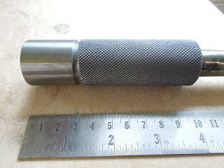
Once this was done my attention turned to the die holder handle. Having decided on the diameter to suit my hand ergonomically.I did not have a suitable diameter bar so I had to turn down a length of oversize, rusty bar to a suitable diameter, bore it (many of my friends would say I only have to talk to it to do that!) and then knurl it before parting off an oversize length making allowance for final facing off.

I did not have a suitable diameter bar so I had to turn down a length of oversize, rusty bar to a suitable diameter, bore it (many of my friends would say I only have to talk to it to do that!) and then parting off an oversize length making allowance for final facing off.
I mounted the bored bar in he chuck and then used the mandrel I had mounted in the tailstock to support it as in the picture above. I use a clamp style Knurling tool, this style puts no lateral forces on the bar so the mandrel was only lightly loaded in ensuring alignment as an insurance.

Setting knurl tool at 90 degree to the bar

First pass to prove alignment of the knurl tool.

Final Handle
The next task was to make the actual die holders, this involved basic plain parallel turning and boring. The basic blank is turned externally with the stub which enters the handle is turned first then the blnk is reversed in the jaws and the large diameter turned. It is then through drilled with an 8 mm drill and then step drilled to the depth of the die up to 25/64" and the diameter finished up to 13/64" with a boring tool or up to 1" for teh larger die. The bore must be a couple of thou' oversize in order to allow the die to spread for a first cut.

Rough Turning Blank for Die Holder

Using Rotary Table for Drilling and Tapping Holes for Die Grub Screws
There are three holes drilled and tapped for the die adjusting and locking screws. There is a central one for the central adjusting screw and two other at 45 degrees each side to lock the die in position. This was done on the milling machine using the rotary table and lathe chuck. In order to ensure that the holes were accurately tapped, a ball ended small milling cutter was used to spot a centre hole, the hole was then drilled with the tap drill without moving the table. It was then partially tapped with a taper tap fixed in the chuck and turned by hand. This was repeated twice at 45 degree centres to give the three holes. The tapping was then completed at the bench vice.
I cut a short length of thread in the lathe and found it successful. So I then made a new one piece mandrel and a handle which may be useful when cutting larger threads.

Die Holder Components

Assembled Die Holder

300 mm Length of Cut Thread With Enlarged Inset
No comments:
Post a Comment