Foundry Work 1
Building a Furnace
Working with hot metal and flammable materials is dangerous and can be fatal or cause life changing injury if not undertaken by a competent person. I have been trained and have been involved in foundry work in the past. This blog is simply a description of what I have done and the contents are not intended as instructions. I advise you not to undertake foundry work until you have had proper training with a qualified person.
For some time I have wanted to carry out some foundry work to supplement my model engineering hobby (and perhaps make a bit of cash on the side? I have some experience in foundry work as when I first started teaching I taught workshop subjects, metalwork and woodwork, to secondary school pupils. In order to be able to do this I had to take courses in foundry work and safety. At least I did teach such subjects until the introduction of the so called 'National Curriculum' imposed by the Conservative Governments of the 1980s following which many school workshops were stripped of their equipment (expensive machine tools, equipment and accessories often sold off for scrap value!). Fortunately the NC has been slowly dismantled over the years.
I have an old graphite crucible - 150 mm across top - and decided to size my furnace accordingly. I chose to use an old damaged gas cylinder as the basis of the furnace as it was a convenient size. First I made sure that there was no residual gas left in the old cylinder by leaving the valve open for several days, then cut off the brass valve (no sparks using a hacksaw on brass), filled the cylinder with hot water and emptied it several times. While it was full of water after the first fill I plugged the filler hole at the top, turned the full tank over and drilled a drain hole in the bottom about 8mm dia so that I could just let water run through afterwards - no sense in taking chances.
 |
| Cylinder with top cut off |
I cut off the top with a cutting disc in a hand held grinder and initially intended to use the cut of top as a lid, bt that was not to be as I'll explain later. I spent a bit of time preparing the shell of the lid. I welded on a couple of home made Handles made from bent 8mm mild steel bar. and then cut a 50mm hole in the top using a rotary saw in a hand held drill to allow gases to escape but then decided to increase the hole to 100 mm as 50 mm looked far to small. This meant chain drilling and chiselling followed by filing.
 |
Lid Chain Drilled to 100mm |
 |
Drilled Holes Chiselled and Centre Removed |
 |
Next Project Sprockets? |
Waste removed.
 |
Hole Filed, Refractory Supports Welded in and Hole Former in Position |
The hole was filed and the former for the vent hole tried in place. The former is in fact a stainless steel citronella lamp body which just happened to be the right size. However I could have used almost anything of a convenient size as I was not fixed to an exact diameter.
 |
| Measuring Volume With Perlite - Note Handle |
Refractory
As I am working on a restricted budget I decided that for my first furnace I would use homemade refractory. After researching on the Internet I eventually decided to use a recipe by Lionel Oliver on his great web resource which he had used for various aluminium melting furnaces using Portland cement, silica sand, perlite and fireclay. I had seen a recipe using just fire cement and perlite and I first tried this recipe but my inexperience in this refractory making led to a disastrous first attempt as casting the resulting 'refractory into the lid as a test - but more of that later.I found a source of inexpensive fireclay and perlite on eBay UK and these cost me around £30.00 at the time, including postage and provides enough material for approximately two furnaces such as I am building so if I find problems with my first attempt I have plenty of surplus.
Now came my first mistake. I confused 'fireclay' with 'fire cement'. I duly and carefully measured the correct proportions of fireclay and perlite as per Myfordboy's instructions and rammed the requisite amount into the lid. Two days later it had not hardened and tried to fall out when I turned it over. Only the supports stopped it falling completely out.
 |
| Lid With Fireclay/Perlite Admix Carefully Prepared. |
 |
| Two Weeks Later - Not Set |
 |
| Fireclay/Perlite Admix still Friable |
New Lid
 |
Fabricated Lid From Mig Welded Sheet Steel |
he rim was cut to length with a generous allowance for overlap. As I no longer have access to a set of rolls I bent it roughly to shape and formed it by tacking one end to the lid with mig welding, then bending it to a close fit for 50 mm and then tacking again and repeated this until the whole rim was attached to the top of the lid. I overlapped the excess, clamped it to the rim and welded it into place. I also bent up and welded on a couple of handles.
 |
Support Ring From Recycled Steel Bar |
To improve the support for the refractory I bent up a hexagon from some 8mm recycled ms bar. The bar is really rough and this improves the grip of the refractory. I welded on four short 'legs' and two longer legs. The latter were then welded to the rim about 25mm from the top. I was going to call it a 'spider' but they have eight legs and calling it an 'ant' is just wrong and against the natural order of the Universe.
 |
Fits Nicely. |
I let out a sigh of relief when the lid worked out ok! Not too many more cock ups I hope. I had added a mechanism to the rear of the furnace (upper right) which you can just make out a part of, this is to add a possible lid lifting and hinging system if I decide to add a bit more sophistication to the furnace later.
If you look carefully you and also make out the burner bracket and the three legs I welded on to the main body shell to lift it a bit higher off the ground. I have made a 50mm drain hole in the base of he shell in case of crucible failure and thought that the extra height that the legs give would allow for any possible spillage.
The next job was to mix the refractory to the new recipe which was:
- 1.5 parts Portland cement (see note below),
- 2 parts silica sand,
- 1.5 parts perlite, and
- 2 parts fireclay.
I measured and mixed the correct quantities of refractory as I completed each part i.e.
- The lid,
- the base of the body, and
- the walls of the furnace.
I dry mixed all of the ingredients really thoroughly on a builders 'spot', a large HDPE tray with raised rim all round made for mixing mortar etc. I then added water a little at a time until I had a rather sticky mixture approximately the consistency of rough dough (why, in English is it pronounced 'ruff dow' and not 'ruff duff' or 'row dow') I can never understand our pronunciation rules!).
I filled the lid first simply by packing it in well and then tamping well down with a short length of 2 x 1 timber. I took a lot of car with this to try and remove as much air as possible and produce a consistent fill with no voids. I forgot to take pictures during the mixing of the refractory and the filling of the lid but I have some of the finished lid.
 |
Completed Lid Finished With Heat Proof Oven Paint |
 |
| Underside of Lid Showing Refractory Fill |
I had just about a large mug full of refractory left over so I shaped that into small blocks which I can use as crucible stands in the furnace if necessary
Main Body
The shell was prepared by drilling and filing a hole 100mm up from the bottom of he shell 50mm diameter shaped to allow the tuyere (fire tube) to run in at an angle. and then a burner support bracket was bolted to the side, with a 50mm hole to allow the former for the fire tube to pass. This will later be reduces to around 22mm with a separate plate to support the burner tube. I also added brackets for a possible lid hinging and lifting mechanism if deemed necessary later. |
Main Body Shell Showing Brackets and Leg |
This view shows the lid lifting and hinging mechanist, The part that looks like a 'tee' handle at the left is actually a welded vertical tube with a second tube loosely fitted inside with a piece of square tube welded across that loose tube and this will swivel in the welded tube. The two black marks are registration marks with the original lid to locate it accurately but I changed the design so they are redundant.
 |
Burner Support Bracket |
This view shows the welded on legs of square tube and the burner support bracket (hole to be reduced in diameter with a reducer plate after casting the refractory.
A few nuts and bolts were added around the upper part of the shell protruding inwards to support the refractory later.
I created an inner former out of some thin stainless steel sheet from an old kitchen bin. To reinforce and support the cylindrical shape I built a central core out of mdf disce and come corrugated card stacks. The latter glued together in stacks of five to make profiling easier.
 |
Card and MDF Discs |
One mdf discs was accurately marked out and carefully cut out on my bandsaw. The other wooden discs were marked using the first as a template to ensure consistency (more important than extreme accuracy). The corrugated card stacks were made from squares of card, glued in stacks of fivewich were then markled out using the remplate and again cut on the bandsaw.
 |
Central Support Core Built - Card Stacks Are Free To Move. |
 |
Thin Stainless Steel Wrapped Around Core |
A ratchet was used to pull the sheet tightly around the core and then tacks used to secure it to the core wooden discs and then these were covered and reinforced by very strong adhesive tape.
Again I took no pictures of the filling process but this is the consistency of the refractory mix:
 |
Small Test Mix of Refractory |
The bottom of the shell had been drilled to 50mm diameter for a drain hole in case of crucible failure and molten metal spills. A tube of silicone sealant was used to act as former for the drain hole in the refractory, this tube was also used to locate the bottom of the main former when the wall was filled.
 |
Silicon Tube and Drain Pipe used as formers |
 |
| Detail of Former For Tuyere |
The shape of the tuyere former had been determined by graphic methods, I had to go back over 50 years to remember how to do the development.
 |
| View Showing How Tuyere Former Fits Against The Main Chamber Former |
The first stage was to fill the refractory to the level of the bottom of the drain hole. This was levelled and smoothed and I knew that the bottom of the main former would help level the bottom when the walls were filled and tamped. The the main former was located over the drain hole former which had been centralised. A prepared length of 32 mm plastic drain pipe was then inserted into the burner hole to form the tuyere (generally pronounced 'twee' in the British foundry).
The top of the main former was located with three wooden blocks accurately cut to be a tight fit around the top. I took great care to get the refractory well packed around the tuyere former and then gradually packed in layers of refractory about 50mm thick. Each layer was carefully tamped with my wooden 'tamper' (rather a posh name for a stick) until I considered that it was well packed in. This continued until the wall was full. The top was levelled and smoothed with a trowel and of course the wooden locating blocks had been removed when the wall was about 2/3rds full.
 |
| Completed Refractory Fill With Main Chamber and Tuyere Formers in Place |
 |
| Formers Partially Removed |
I removed the formers after allowing the refractory to cure for about a day and a half. The tuyer former came out easily as it had been wrapped in it's paper template - (make note for the future). In order to remove he main former I had to first remove the supporting core discs. The top one was levered out with a couple of screwdrivers and a small wrecking bar - I had cut each wooden disc radially to allow this. The card stacks just lifted out and I was able to remove the central disc by cutting a second cut with a compass saw and then could lever up one half of the disc and easily remove the second half and the remaining card stacks. The bottom one was a bit more difficult, I had not really thought the problem through. I finally took a 25mm wide wood chisel and cut 'trenches' almost through the disc. I could then lever up the two halves and the sides stainless sheet could be twisted inwards to reduce the diameter and carefully lifted out.
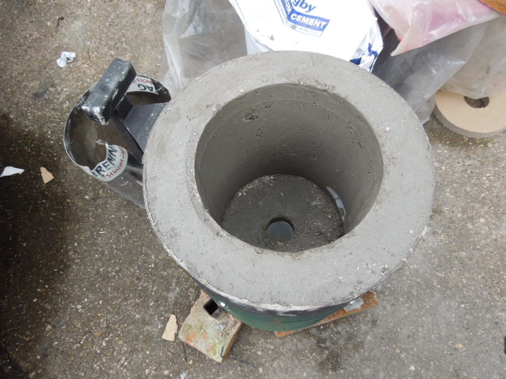 |
| Formers removed |
Success! The furnace lining looks pretty good apart from a few surface blemishes. Now I just need to let it dry before conditioning by repeated firings. The first at about 200° C and gradually increasing temperature and letting each one cool fully to room temperature.
 |
Minor blemishes |
There are a few small blemishes in the wall which I don't think will cause a problem but I will fill them just in case.
 |
Blemishes Filled |
I used a fireclay/Portland cement mixture made into a stiff paste with a little water only time will tell if there is a problem with this.
 |
| Lid tested in place |
No comments:
Post a Comment